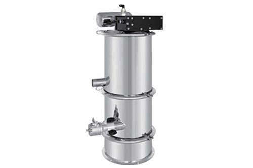
Vacuum conveying system works on a cyclic operation where the system conveys for a set time or to a level, conveying stops, the discharge valves opens and the filters are cleaned. This sequence is then repeated. Continuous transfer can be achieved by utilising a rotary valve at the outlet of the receiver.
The product is introduced at the pick up point into the conveying line by various equipment such as suction lance, feeding hoppers, feeding screws, rotary valves, extruders etc.
The necessary gas flow is generated by the vacuum generator located at the far end of the line, after the vacuum receiver and thus the material is sucked through the pipeline and into the vacuum receiver.
In the vacuum receiver the gas is then separated from the product by flowing through a filter which rejects the solids. During every discharge cycle the filter is automatically cleaned via a compressed air blast.
Specifications
| Model | AVC-N1 | AVC-N2 | AVC-N3 | AVC-N4 | AVC-N5/6 | AVC-N7 | AVC-N10 |
| Delivery Pressure | 0.6Mpa | 0.6Mpa | 0.6Mpa | 0.4Mpa | 0.6Mpa | 0.4-0.6Mpa | 0.6Mpa |
| Air Consumption | 0.5~0.8Mpa approximately10L/min | ||||||
| Capacity | 200KG-400KG/h | 400KG-600KG/h | 800KG-1100KG/h | 1200KG-1500KG/h | 2500KG-3200kg/h | 4000KG-5500KG/h | 5000KG-6000KG/h |
| Vacuum pump power | 1.6KW Twin turbo | 2.2KW Twin turbo | 3.0KW Twin turbo | 4.0KW Twin turbo | 5.5KW Twin turbo | 7.5KW Twin turbo | 7.5KW Triple turbo |
| Inlet size | Φ38 | Φ38 | Φ51 | Φ51 | Φ51 | Φ63 | Φ76 |
| Outlet size | Φ210 | Φ210 | Φ290 | Φ290 | Φ290 | Φ420 | Φ420 |
Common Applications
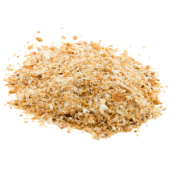
Breadcrumb
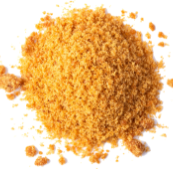
Brown-Sugar
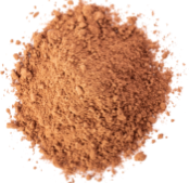
Cake-Mix
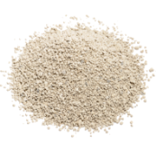
Cat Litter
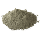
Cement-Powder
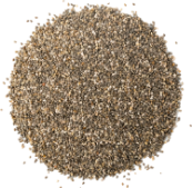
Chia-Seeds
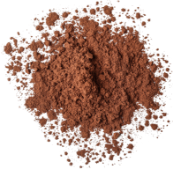
Cocoa-Powder

Cosmetics Powder
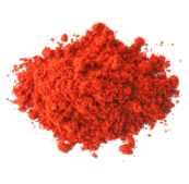
Curry-Powder
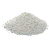
Detergent-Powder
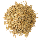
Fennel Grass-Seeds
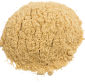
Food Powders
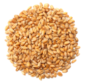
Grains
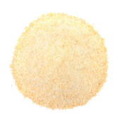
Ground Spices
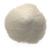
Infant Formula
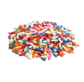
Jimmies Sprinkles
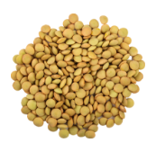
Lentils-Seeds
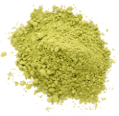
Matcha-Powder
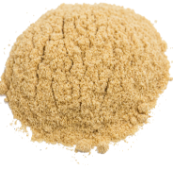
Pancake-Mixpng
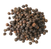
PepperGround Pepper
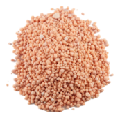
Plant Foods
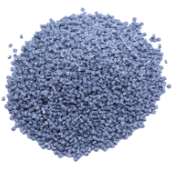
Plastic Granules
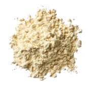
Protein-Powder
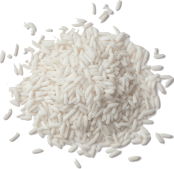
Rice-Powder
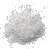
Salt-Products
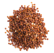
Seeds
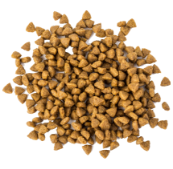
small Pet Food
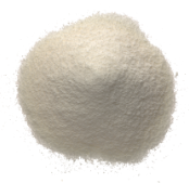
Sugar
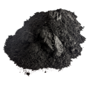
Toner Powder
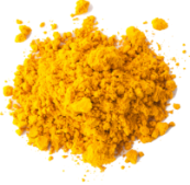
Turmeric-Spices
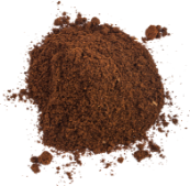
wholeGround-coffee

Milk Powder
videos


